

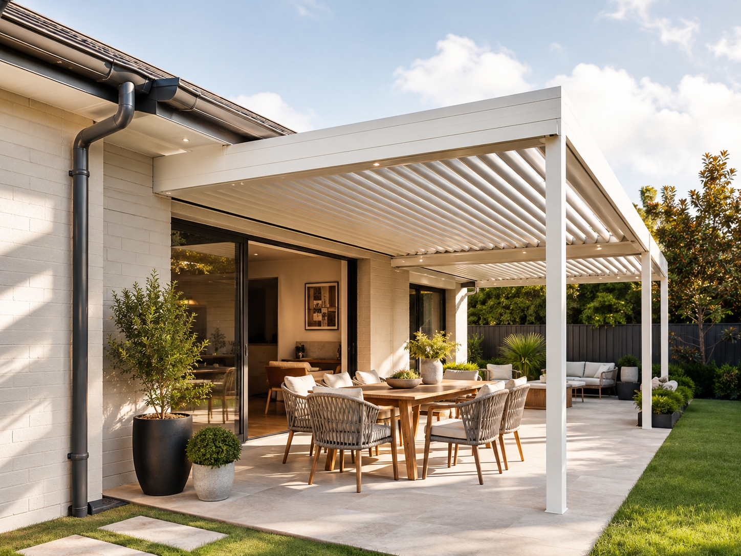
Before choosing the position of a new patio roof, draw the water routes that already exist. Mark the house-roof fall, every gutter run, each downpipe, nearby stormwater points, paving falls and the places that stay wet after rain. That sketch is more useful than starting with a product size, because the new structure must sit beside a working drainage system rather than pretend the system is not there.
A rear wall can look clear on a dry afternoon and still be crowded once the upper half is studied. A downpipe may turn behind a shrub, a gutter outlet may sit above the preferred connection line, or paving may fall back toward a sliding door. The sensible position is firm: map the existing water movement before deciding whether a wall-mounted, freestanding or customised louvred structure can fit without blocking access or creating an awkward discharge point.
Site-planning boundary
This guide explains what to record and compare. It does not provide drainage engineering, structural fixing details or a compliance conclusion. Existing stormwater, wall connections, ground falls and any proposed discharge arrangement require confirmation on the actual property by the appropriate installer, drainage professional, engineer, building professional or approval authority.
Map Existing Roof Drainage Before Positioning a Patio Roof
Start at the highest visible point of the house roof and follow water all the way down. The roof pitch or valley direction shows which gutter sections receive the heaviest flow, while gutter outlets reveal where that flow enters the downpipes. On a typical rear elevation, this five-minute tracing exercise often explains why one corner stays dry and another develops a puddle after a short storm.
Next, record each component on a simple plan. A phone photo can carry numbered notes: “1” for the left gutter outlet, “2” for the downpipe beside the kitchen window, “3” for the grated drain near the step and “4” for the low patch in the paving. The drawing does not need architectural polish; it only needs enough detail for the complete route to remain visible when pergola sizes are compared later.
The roof above the gutter matters
A gutter is the visible collection line, yet the roof above determines how much of the house drains into it. A short rear gutter beneath a large roof plane may matter more than a long side gutter serving a small section. During steady rain, observe which outlets run strongly, which corners overflow and whether leaf guards, trees or roof valleys concentrate debris in one place.
Also note any lower roofs, verandas or extensions that feed into the same area. A laundry roof may discharge into the main rear gutter, while an older awning may release water directly onto the paving. These secondary flows can be easy to miss in a clean plan, although they become obvious when water tracks across the surface for ten or fifteen minutes.
A downpipe occupies more space than its footprint
A downpipe is not just a point on the ground. Its upper offset, brackets, bends and connection to the gutter occupy vertical space, and that space may overlap a beam or wall-mounting zone. Photograph the entire pipe from gutter to ground, then take one side view so the distance from the wall and any offset around eaves can be understood.
Where a pipe disappears into paving, soil or a rainwater system, record that transition without assuming what happens below ground. Where it discharges above ground, photograph the outlet and the next two or three metres of surface. A splash block, garden edge or open grate may look minor, but moving the covered footprint can change how often that area becomes wet.
Rain shows what a dry inspection misses
Dry paving hides low points. After rain, darker patches reveal slow drainage, fine silt marks show where water has travelled, and a line of leaves can identify the edge of repeated flow. A photo taken ten minutes after the rain stops and another an hour later can be more informative than several photos taken on a bright day.
Safety matters more than the photo. There is no need to stand beneath overflowing gutters or walk on slippery surfaces. A photo through a window, a short video from the doorway or an inspection once the storm has eased can capture the same evidence without turning a planning exercise into a risk.
Drainage map checklist
- House-roof pitch, valleys and lower roof sections.
- Gutter direction, outlets, corners and visible overflow points.
- Full-height downpipe locations, bends, brackets and ground connections.
- Grated drains, pits, garden outlets and rainwater-system components that are visible.
- Paving or deck falls, puddles, splash zones and slow-drying corners.
- Door thresholds, steps and walking lines that should remain clear and comfortable.
Avoid Blocking Gutters and Downpipes
The new frame should not turn routine gutter work into a difficult job. Leaves still need to be removed, outlets still need to be checked, and a downpipe may need repair years after the pergola is installed. A beam positioned tightly under a gutter or a post placed directly in front of a pipe can make ordinary access slower, messier and more expensive.
Maintenance access is often lost in drawings because every line appears thin. On site, a hand, ladder, tool and replacement fitting need real space. Even a visually neat gap can be impractical when a gutter bracket sits behind the frame or a downpipe coupling cannot slide apart without removing another component.
Leave the gutter serviceable
A wall-mounted layout usually brings the new structure close to the eaves, so the relationship must be viewed from below and from the side. Record the underside of the gutter, the fascia depth, the soffit line and any gap between the gutter and wall. A single front-on photo can hide a projecting bracket or a gutter profile that sits farther out than expected.
The aim is not to invent a universal clearance number. Buildings, gutter profiles, connection methods and maintenance needs differ. Instead, the aim is to provide enough visual and measured information for the appropriate professional to decide whether the proposed beam line preserves workable access.

A downpipe is not spare space
A downpipe carries house-roof water before the new structure is considered. That role should remain clear in the plan. A post cannot simply occupy the same line because both elements appear close to the corner, and a beam should not trap a pipe against the wall where brackets or joints become inaccessible.
Where the pipe sits inside the preferred footprint, there are several planning directions, but none should be assumed from a photograph alone. The pergola position may shift, the post grid may change, a freestanding arrangement may create cleaner separation, or a properly designed service alteration may be considered by the relevant professional. The wrong response is to hide the conflict and hope it disappears during installation.
Corners deserve a wider look
Corners collect more than visual clutter. Gutter mitres, stop ends, outlets, downpipe bends, fascia returns and roof-valley discharge can all meet within a small area. Placing a pergola corner in the same zone may create a dense stack of parts that is hard to inspect and harder to clean.
A practical check uses a one-metre-wide photo around every proposed rear corner. Include the ground, wall and roof edge in the same frame where possible. That wider view reveals whether a post would also crowd a garden tap, exterior light, hose reel, air-conditioning line or narrow side passage.
A beam or post location is not ready to confirm if it permanently removes access to an existing gutter or downpipe. The layout needs another look when ordinary cleaning or repair cannot be carried out without dismantling the new structure.
Where Water From the Patio Roof Needs to Go
A louvred structure has its own water path, and that path must be considered beside the house system. When the blades close, overhead rain is directed toward the frame channels and then toward the system’s intended outlets. The planning question is not merely whether water leaves the louvres; it is where that water reaches the site after it leaves the structure.
The safest starting assumption is separation. House-roof drainage and pergola drainage are two systems until a suitable professional confirms how the project should handle them. Joining, redirecting or altering existing stormwater is not a product-selection detail, and it should never be improvised from a general diagram.
This article focuses on fitting the new structure beside the home’s existing water routes. For a closer explanation of blades, channels and the pergola’s internal roof-water path, see how louvered pergola drainage manages rainwater.
Trace water past the frame
Water management has four visible stages: collection on the closed louvres, movement through the roof edge, travel through the frame’s intended drainage route and release into an appropriate site arrangement. A plan that stops at stage two is incomplete. The last metre often matters most because that is where water can meet paving, soil, a threshold, a step or an already wet corner.
For example, a roof outlet near the outer garden edge may appear reasonable on paper. Yet the same point becomes awkward if the paving falls back toward the house or if the outlet sits beside the only path to the clothesline. A second example is a release point near a side gate; the water route may be technically outside the seating area but still cross a high-use walking line.
Plan for outdoor exposure, not an indoor-room promise
A louvered roof system can help manage overhead rain when the blades are closed and the drainage route is maintained. Even so, an outdoor structure remains exposed at the sides. Wind-driven rain, splash, intense weather, debris, open edges and the condition of the ground all influence how the area behaves.
That distinction matters near doors and glazed openings. The goal should be a sensible, confirmed water route rather than a broad claim that every surface will remain dry in every storm. Furniture placement should also allow for side exposure, particularly where low wind can push rain beneath a covered edge.
The outlet position matters before colour does
Colour and accessories can wait. Before those choices, mark two or three possible water-release zones on the site plan and test each one against everyday movement. Reject any option beside a door threshold, at the top of a step, under a dining chair, next to an outdoor power point or over paving that already drains poorly.
Also look beyond the covered footprint. A release point may avoid the table but send water toward a neighbouring path, a garden retaining edge or a narrow gap between buildings. The appropriate professional can then assess the actual drainage condition, while the product conversation remains grounded in a layout that makes practical sense.

Reject a proposed release zone when it:
- Sits beside a sliding-door or hinged-door threshold.
- Falls across the main path between the kitchen and outdoor table.
- Adds water to a corner that already puddles after moderate rain.
- Crowds a downpipe, drain grate or service that requires access.
- Directs water toward a step, pool edge, retaining wall or narrow side passage.
Wall-Mounted Connections Near Eaves
Wall-mounted planning needs a complete elevation, not a close-up of one brick or one section of cladding. The relevant zone usually includes the roof edge, gutter, fascia, soffit, visible wall finish, doors, windows, lights and services. A photograph that cuts off the eaves removes the very information that may decide whether the preferred position is workable.
The connection itself must be determined for the actual building. Visible brick, render, cladding or fascia does not prove what can support a structure, and this article does not propose a fixing method. The practical contribution at the planning stage is accurate context: clear photos, measured heights and an honest record of every obstruction.
Read the whole eave line
Stand far enough back to include both upper corners of the intended area. The frame should show the gutter line, the ground surface and all openings between them. Then take separate close-ups of each downpipe, gutter outlet, eave return, external light and service line that crosses the proposed width.
A useful photo set usually includes one front view, one view from the left, one from the right and one taken from inside the adjoining room. The inside view matters because a beam that clears the door may still interrupt the upper part of the glazing or make a low eave feel visually heavy. This is a design observation, not a structural conclusion, but it can prevent an uncomfortable proportion from being locked in too early.
Measure the vertical stack at both ends
Measure from the finished ground or deck surface to several points: the door head, window head, underside of the soffit, underside of the gutter and any visible proposed connection zone. Record the numbers directly on a copy of the photo. A measurement written in a separate message is easy to misread, while an annotated image makes the reference point clear.
Floor levels can change across a rear wall. A patio may slope 30 or 40 millimetres across a short run, or one section may sit on a raised deck beside lower paving. For that reason, take vertical measurements at both ends rather than assuming one number applies across the whole width.
Measure openings and services, not just the wall
Doors and windows occupy space while moving. An outward-opening door, awning window, security screen or exterior shutter can conflict with a beam even when the closed opening appears clear. Photograph the element both closed and fully open, then measure the highest or furthest point of its movement.
The same rule applies to roller shutters, retractable awnings and clothesline arms. A component used only once a week still needs room to operate. Removing that function after installation is a poor trade for a visually centred frame, especially when a small layout shift could preserve it.
Small wall details can change the layout
External conduits, vents, meter boxes, hose taps and air-conditioning lines can reveal where services run, although their exact route should not be guessed. Photograph these features and include any available building drawings in the discussion. Cutting, moving or covering a service is not a casual site adjustment.
When the eave zone is crowded, a freestanding arrangement may deserve comparison. Separating the new frame from the building can sometimes preserve gutter and service access, although posts, footing conditions and ground drainage still need their own assessment. The important point is to compare the whole site rather than force every project against the wall.

Photos and measurements to prepare
- Full wall, eaves, soffit, fascia and gutter line.
- Every gutter outlet and downpipe within or beside the planned width.
- Door and window heights, plus photos of outward movement.
- Ground-to-eave measurements at both ends of the proposed structure.
- Visible lights, vents, taps, conduits, meter boxes and air-conditioning services.
- A view from inside the adjoining room to show light and sightline effects.
Ground Drainage Around Posts
Post planning is not only a structural grid exercise. Each post meets a real surface that may slope, crack, hold water or conceal drainage. The ground around the base should be studied after rain, because a position that looks clean when dry may sit in the exact line where water crosses the patio.
The post should not become a dam. On paving, water can collect against the uphill side of a base if the surrounding fall is poorly understood. Near soil or garden beds, mulch and sediment may move toward the post area, while a nearby grate may need clear access for cleaning.
Watch where the paving already sends water
A long spirit level or professional survey provides better information than appearance alone, but early observations still help. Look at grout lines, paving edges and the route taken by a small amount of rainwater. Chalk marks placed after a storm can show the edge of a puddle and make its size easier to compare the next day.
Do not pour large volumes of water onto an uncertain surface merely to test it. Existing drainage problems may send water toward the building or into a neighbouring area. Natural rainfall evidence, available plans and professional assessment are more appropriate where the fall is unclear.
Keep drains and inspection points usable
A grated drain needs room above and around it. A post, base plate, screen track or fixed cabinet should not make the grate difficult to lift or the channel hard to clean. The same caution applies to inspection openings and visible stormwater access points, even when they sit near the visually convenient corner of the pergola.
Mark every drain on the measured plan before furniture is added. This order matters because a dining table can be moved later, while a post position cannot be casually shifted after the project has been designed. A clear plan also prevents a grate from disappearing beneath a sofa in the final visual layout.
Protect thresholds, drains and post zones
The area just outside the main door deserves special attention. This small zone carries plates, drinks, children, pets and wet shoes, often several times in an evening. Adding a post, water outlet or persistent puddle there can make the entire covered area feel less convenient, even if the rest of the footprint is generous.
A practical layout keeps that transition visually open and gives water another route. Where existing paving already falls toward the threshold, the issue should be assessed before the pergola is chosen. Overhead cover cannot repair an underlying surface-drainage problem by itself.
Check the post grid against daily movement
Set out the intended table, barbecue or lounge footprint with removable tape. Pull a dining chair back by roughly the distance used in normal movement, then walk from the door to the garden. If the path squeezes between a chair and a proposed post, the plan will feel tighter in daily use than it appears on a clean drawing.
This test also helps keep drainage outlets away from occupied edges. Water released beside the back leg of a chair or behind a barbecue creates an inconvenient maintenance corner. A small change in post position or overall dimension may improve movement, cleaning and water management at the same time.
Ground check for each proposed post
- Photograph the dry surface and the same area after rain.
- Mark nearby grates, pits, cracks, steps and changes in level.
- Confirm that the base will not obstruct cleaning or an inspection point.
- Test chair movement, door access and the main walking path.
- Ask the appropriate professional to confirm the surface, support and drainage conditions on site.
When Custom Planning Is Worth It
Custom planning becomes worthwhile when a standard rectangle forces a known conflict. Common examples include a downpipe inside the proposed post line, a low eave above one side, an outward-opening door near a corner, an offset paving edge or a drain that must remain accessible. In these situations, adjusting the structure around the site is usually more sensible than accepting a poor water route for the sake of a nominal standard size.
The threshold is practical, not decorative. A colour preference alone does not make the project complex, while a 150-millimetre clash with a downpipe can affect access and drainage for years. When standard dimensions create that sort of conflict, the customise your pergola pathway provides a relevant starting point for discussing width, depth or height around the real site.
A standard size can still create a bad fit
A standard model is not automatically a simple installation. It may fit the measured width yet overlap the gutter maintenance zone, place a post beside a drain or direct the outer edge toward a low point. Product dimensions and site suitability answer different questions, so both need attention.
Customisation also should not be treated as a way to avoid site assessment. Changing a width can resolve a spatial conflict, but it does not confirm the wall, footing, drainage or approval condition. Those decisions still belong to the appropriate people after the actual property has been reviewed.
Compare P180 and P180 Pro by footprint and roof configuration
For many everyday dining or lounge areas, a standard-size discussion can start with the P180 aluminium pergola, because wall-mounted and freestanding configurations can be compared against the same drainage map. Current standard options run from 3 × 3 m to 3 × 10 m and include manual or motorised louvres. A size that works on paper only matters when the gutter, downpipe, door and ground conditions leave a workable position.
P180 Pro adds motorised double-layer louvres and includes 4 m-deep options such as 4 × 4 m, 4 × 6 m and 4 × 8 m, alongside selected 3 m-deep sizes. It may enter the discussion when the measured living zone needs that extra depth or roof configuration—not simply because the yard looks large in a photograph.
More covered area also means more roof area interacting with rain, so the release route and post grid deserve closer attention, not less. Model choice alone does not confirm stormwater capacity or the suitability of a discharge point; those conditions still need to be checked for the project.

Compare more than one footprint
Instead of defending one preferred footprint, sketch three. Layout A can follow the ideal furniture zone, Layout B can move away from the downpipe, and Layout C can test a freestanding position that leaves the eaves untouched. Comparing the three plans often reveals that the original idea is not the only workable one.
Each plan should carry the same information: post positions, door swing, gutter outlets, downpipes, drains, paving fall, furniture and walking lines. A layout wins only when it performs across all of those layers. Visual symmetry matters, but access and drainage should break a tie.
When a standard size starts fighting the site
Several warning signs appear repeatedly. One post needs to sit directly in front of a downpipe; the beam nearly touches the gutter; a drain grate disappears below the frame; the main door opens into a corner; or the only available outlet lies beside an existing puddle. Any one of these is a reason to pause and redraw.
Another sign is excessive reliance on future alterations. If the plan works only after the gutter is moved, paving is regraded, a pipe is rerouted and a service is relocated, the supposed standard solution is no longer simple. The scope should be reviewed as one project, with each alteration assessed by the relevant professional before the pergola configuration is confirmed.
Custom planning earns its place when it solves a measured conflict involving eaves, downpipes, doors, drains, paving edges or circulation. A different size is useful when it improves the fit of the whole site, not simply because a non-standard dimension sounds more tailored.
What to Photograph and Measure Before Comparing a Layout
A useful planning set does not need dozens of close-ups. One wide photo should show the complete rear elevation from ground to gutter, followed by clear images of each downpipe, gutter outlet, drain and wet corner. If the site changes level, add a side view so the paving fall or step is easy to read.
Measurements should answer the conflicts raised in the photos. Record the usable width, preferred projection, ground-to-eave height at both ends, door and window heights, downpipe offsets from the nearest corners and the distance to visible drains. Include the dining table, lounge setting or barbecue footprint as well; a post that technically fits may still sit in the worst place for daily movement.
A useful handover usually includes
- one full-elevation photo showing wall, eaves, gutter and ground together;
- close-ups of downpipes, outlets, drains and any visible ponding;
- height measurements at both ends, not one assumed level;
- rough width, projection and the main furniture or walking zone;
- a note stating whether wall-mounted, freestanding or both layouts are open for comparison.
That small set is enough to make the next conversation specific. It shows where the existing house drainage sits, where a frame might clash, and which dimensions actually need discussion. It still does not replace an on-site assessment for the wall connection, ground condition or drainage arrangement.
Frequently Asked Questions
Can a patio roof be installed near existing gutters?
It may be possible, but “near” is not enough information for a reliable decision. The gutter profile, outlets, maintenance access, eave construction, available height and proposed frame position all need to be reviewed together. A clear photograph of the complete roof edge is the starting point.
The building connection and drainage arrangement require confirmation for the actual property by the appropriate professionals. No standard gap or universal fixing assumption should be applied from a general article.
What happens if a downpipe is inside the planned pergola area?
Treat it as a real layout conflict, not a detail to hide later. The proposed width, post position or configuration may need to change, or a properly assessed service alteration may form part of the wider project. The pipe should remain accessible unless the relevant professional confirms another arrangement.
Photograph the full pipe, including bends, brackets and the ground connection. Then compare at least one alternative footprint before deciding that the original position must be preserved.
Where should water from a louvred roof be directed?
The intended route should avoid doors, steps, principal walkways, occupied furniture edges and existing puddling zones. It should also make sense beside the house gutters, downpipes and visible stormwater points. The final discharge or integration arrangement must be confirmed for the property rather than inferred from a product image.
A useful early plan marks several possible release zones and rejects the obviously poor ones. The remaining options can then be checked on the actual property.
Does a wall-mounted layout need extra drainage checks?
Yes, because the new structure sits close to the house roof edge, openings and existing services. The assessment should consider gutter access, downpipe positions, eave height, the building connection zone, threshold drainage and the direction of the ground fall. These checks are additional to the pergola’s own water path.
A wall-mounted option may still be suitable, but the decision should come from the complete site picture. When the upper wall is crowded, a freestanding comparison can be useful.
When is custom planning needed around eaves and downpipes?
Custom planning is useful when a standard width, depth or height creates a measured conflict. Examples include a post overlapping a pipe, a beam crowding the gutter, a low eave on one side, a drain beneath a corner or an opening that loses normal movement.
The purpose is to improve fit around a real constraint, not to avoid site assessment. Structural, drainage, ground and approval questions still require the relevant professional confirmation.
Plan the Existing Water Before Finalising the New Structure
The most reliable patio roof plan begins with what the home already does in the rain. House-roof flow, gutters, downpipes, paving falls and wet corners should appear on the same drawing as posts, doors, furniture and walking routes. Once those layers are visible, unsuitable positions become easier to reject and useful alternatives become easier to compare.
Before a configuration is confirmed, prepare the full-elevation photos, close-ups of every downpipe, measured eave and opening heights, ground-slope observations and images of any puddling. Then contact Everpergo with the preferred use and rough dimensions so the relevant model or custom pathway can be discussed. Connection suitability, stormwater handling, ground conditions and any approval requirements must still be confirmed on site by the appropriate professionals.
Before discussing the final layout
- prepare one full photo of the eaves, gutter and wall;
- add close-ups of every downpipe, visible drain and wet spot;
- record width, projection, both eave heights and nearby door or window heights.
If a standard footprint clashes with those points, compare the custom-size route before forcing the structure into the available rectangle. When the photo set and rough dimensions are ready, contact Everpergo to discuss the relevant P180, P180 Pro or custom configuration. The final wall connection and drainage arrangement still need confirmation on the property by the appropriate professionals.
Share:
Louvered Roof System for Pool Areas: Shade, Ventilation and Splash-Zone Planning
Adjustable Pergola Roof for Morning-Sun and North-Facing Outdoor Areas